ChirpBox provides two sets of permissions: User and Administrator.
This tutorial will show 1) how to prepare an experiment firmware image and 2) how to manage experiments (firmware dissemination and results collection).
You could order ChirpBox nodes by writing mail to us or build a ChirpBox testbed by yourself.
0. Prerequisites
The project is developed with integrated development environment (IDE) STM32CubeIDE.
The source code is available here.
1. User firmware preparation
Please add the Toggle tool in your own project (e.g., a wireless network protocol to be tested), recompile it, and generate the firmware for ChirpBox. Assuming your own project is also developed with STM32CubeIDE, the specific steps would be:
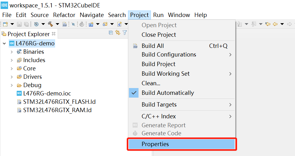
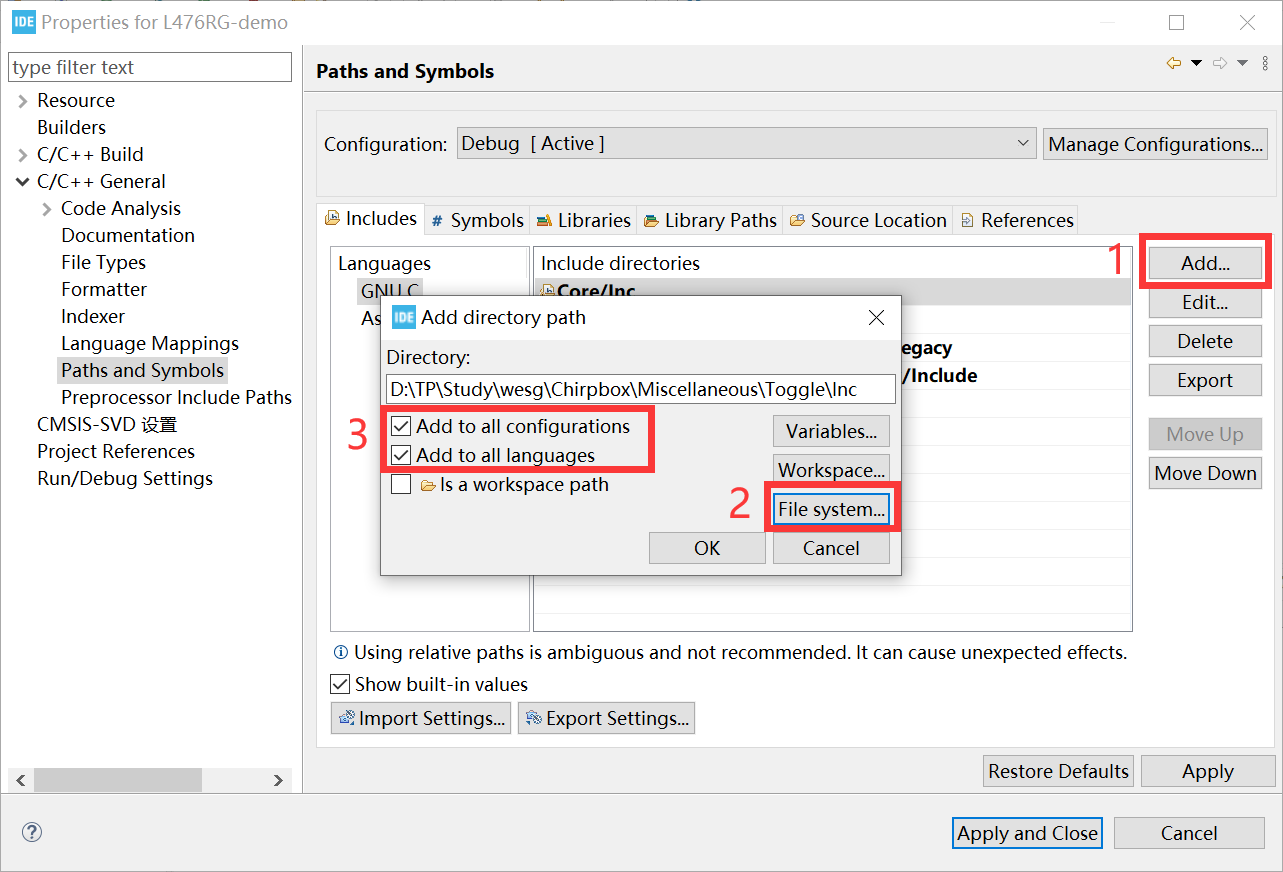
1. Open Project->Properties, go to Paths and Symbols in C/C++ General, add ChirpBox/Miscellaneous/Toggle/Inc/ to the include directories.
2. Add ChirpBox/Miscellaneous/Toggle/Src/ to the source location.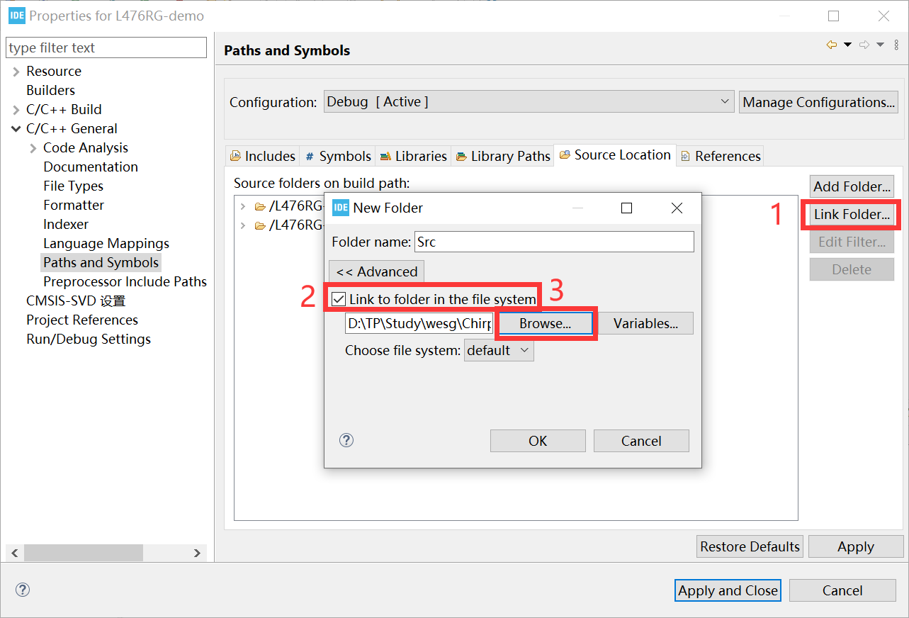
3. Check if the following MCU related files are in your project:
- Include:
stdint.h,stm32l4xx.h,stm32l476xx.handsystem_stm32l4xx.h - Source:
system_stm32l4xx.c - Startup file:
startup_stm32l476xx.s
If some files are missing, these files can be found here.
4. Make sure that -O binary is checked as shown below. Then, compile your own project and generate the .bin file for ChirpBox.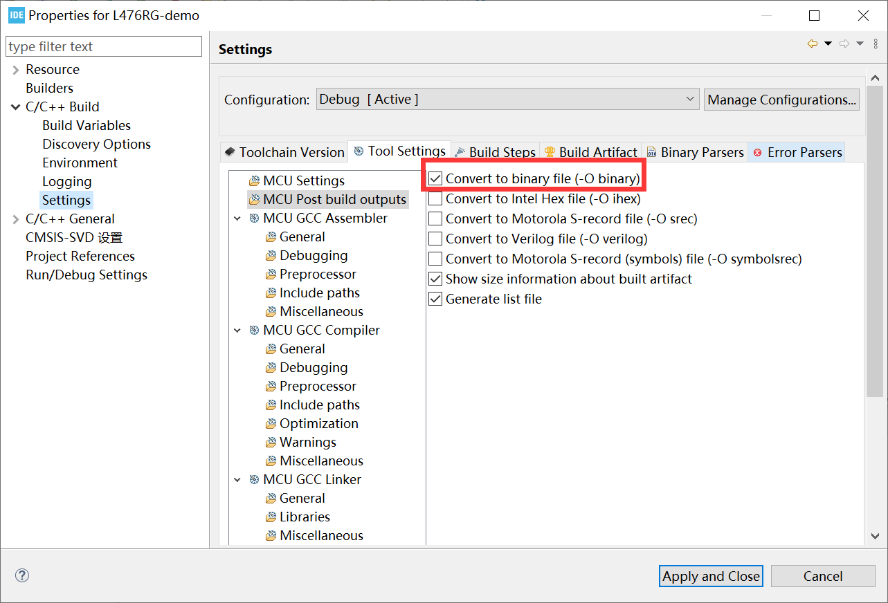
1.1 Example project
ChirpBox provides an example project, which includes all necessary files in Toggle and logs "Hello world" in ASCII format at 0x080FF800 (last page address of the MCU’s Flash).
1. Go to ChirpBox/Miscellaneous/Example/L476RG-demo/, open the .project file with STM32CubeIDE.
2. The L476RG-demo.bin would be under Debug/ after you compile the project.
1.2 APIs for experiments
You are able to achieve multiple functions (e.g., store loggings to the internal flash or energy consumption estimation) in your own project by using APIs provided by ChirpBox. Please see our documentation on APIs for details.
2. Start an experiment with the script
The script provided by ChirpBox requires a Python 3.x. environment.
Make sure that the control node is connected to a computer via serial port.
2.1 Configure the experiment
You can configure the experiment related parameters including experiment duration, name, the flash start address for loggings etc. experiment_duration is in second. For example, the example_config_method.json in ChirpBox/chirpbox manager/ configures experiment named test:
1
2
3
4
5
6
7
{
"experiment_name": "test",
"experiment_description": "This is a test experiment",
"experiment_duration": 1800,
"start_address": "080FF800",
"end_address": "0810000",
}
Please adapt configurations in example_config_method.json according to your own experiments. This file example_config_method.json can be created in another directory or renamed by yourself, but you need to make modification in the ChirpBox/chirpbox manager/cbmng.py.
2.2 Post and start the experiment
To post the experiment on ChirpBox testbed, we need
1) measure the link quality and 2) obtain the topology to make sure all the nodes are connected.
3) Post (disseminate) the firmware under test (the .bin file generated previously) to the target nodes.
Then, 4) start the experiment.
Specifically,
1) Link quality measurement
For instance, you plan to measure the link quality when LoRa radio’s spreading factor (SF) is set to 7 at 470 MHz with the Tx power of 0 dBm. The control node is connected to the serial port COM1 of the computer. The command of link quality measurement is disseminated with SF 8, 14 dBm in 80-packet-slot rounds. The bitmap is 0x1FFFFF (21 bits of 0b1) if there are 21 nodes (including the control node).
1
python cbmng.py -connect 7 470000 0 8 COM1 80 14 1FFFFF
2) Topology collection
For instance, the collection packet size is 128 bytes each packet. The serial port of the control node is COM1. The command is disseminated with SF 8, 14 dBm in 80-packet-slot rounds.
1 | python cbmng.py -coltopo 8 128 COM1 80 14 |
3) Firmware dissemination
For instance, put the generated .bin file to ChirpBox/chirpbox manager/. NOTICE: guarantee only one .bin file is in this directory. The daemon firmware version is 0xabcd which can be obtained by colver command (seeing 3.2 in DIY CHIRPBOX). The serial port of the control node is COM1. The firmware is disseminated with SF 8, 0 dBm, 200-byte packets and 16 packets/round with 80-packet-slot rounds, and the configuration in the all-to-one round followed by each one-to-all round is SF 7, 14 dBm, and 60-packet-slot rounds. Dissemination is transmitted among 21 nodes (including the control node) (0x1FFFFF) but only conducted on 20 target nodes (0x1FFFFE).
The command dissemination parameters cannot be configured in here, which would adopt the previous configuration.
Here, the command would be disseminated with SF 8, 14 dBm in 80-packet-slot rounds since the parameters are configured in the previous step, i.e., the topology collection.
1
python cbmng.py -dissem 0 abcd 200 16 8 COM1 1FFFFE 80 7 60 14 1FFFFF
4) Starting the experiment
Set flash protection flag to 1 among 21 nodes (0x1FFFFF) including the control node. The daemon firmware version is 0xabcd. The serial port of the control node is COM1. The command is disseminated with SF 8, 14 dBm in 80-packet-slot rounds. This command would load the configuration in example_config_method.json automatically.
1
python cbmng.py -start 1 abcd 8 COM1 1FFFFF 80 14
2.3 Get the experiment results
Once the experiment has been finished, we can collect the results.
1) Results collection
For instance, you plan to collect 2048-byte loggings in the flash from 0x080FF800 to 0x0810000 in a block of 128 bytes, i.e., the collection packet size is 128 bytes each packet. The serial port of the control node is COM1. The command is disseminated with SF 8, 14 dBm in 80-packet-slot rounds. Collect data from the 20 target nodes (0x1FFFFE) (except the control node).
1
python cbmng.py -coldata 128 8 COM1 80 14 1FFFFE