You can follow this page to build your own ChirpBox from scratch.
0. Materials
First of all, please prepare the materials which are required to make a hardware ChirpBox node.
A BOM list (.xlsx file) is available here.
- Main components:
- #1. Processor board (STM32 NUCLEO-L476RG) * 1
- #2. LoRa transceiver board (Semtech SX1276MB1xAS) * 1
- #3. GNSS module (NavSpark-GL) * 1
- #4. RTC module (DS3231MPMB1) * 1
- Power:
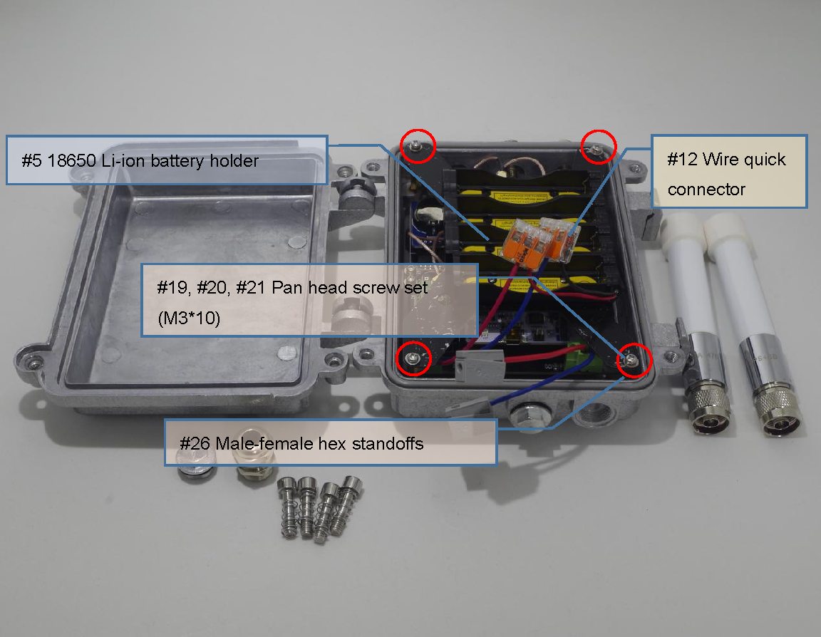
- #5. 18650 Li-ion battery holder (with charging protection; 1S4P) * 1
- #6. 18650 Li-ion battery (Panasonic NCR18650B MH12210) * 4
- Connectors:
- #7. 470 MHz fiberglass outdoor antenna * 1
- Used by the LoRa module [#2]
- N-type connector plug, male pin
- #8. N-to-SMA cable connector * 1
- Connecting LoRa radio signal between the shield [#13] and the LoRa transceiver board [#2]
- 15 cm N-type connector jack, female socket to SMA plug, male pin with nut bulkhead RF coaxial connector (5/8-24 UNEF thread N-K female to SMA-J)
- #9. 1.5 GHz fiberglass outdoor antenna * 1
- Used by the GNSS module N-type connector plug, male pin
- #10. N-to-IPEX cable connector * 1
- Connecting GPS radio signal between the shield [#13] and the GNSS module [#3]
- 15 cm N-type connector jack, female socket to IPEX Gen. 1 with nut bulkhead RF coaxial connector (5/8-24 UNEF thread N-K female to IPEX Gen.1)
- #11. Customized base board * 1
- Connecting the processor board [#1] to the RTC module [#4] and the GPS module [#3]
- Related files are available here
- #12. Wire quick connector (WAGO 221-412) * 4
- Shield:
- #13. Outdoor node shield * 1
- With 5 mounting holes (5/8-24 UNEF thread) for N-type connectors (part number: 03A-C)
- #14. Waterproof plug (5/8-24 UNEF thread waterproof plug) * 3
- #15. Customized mounting plate (used by the battery holder [#5], related files are available here) * 1
- Mechanical parts:
- Pan head screw set (M3 * 7)
- #16. Pan head screw (M3 * 7 mm) * 4
- #17. Flat washer (M3 * 7 * 0.5mm) * 4
- #18. Spring lock washer (M3) * 4
- Pan head screw set (M3 * 10)
- #19. Pan head screw (M3 * 10 mm) * 4
- #20. Flat washer (M3 * 7 * 0.5mm) * 4
- #21. Spring lock washer (M3) * 4
- Pan head screw set (M2 * 5)
- #22. Pan head screw (M2 * 5 mm) * 4
- #23. Flat washer (M2 * 5 * 0.5mm) * 4
- #24. Spring lock washer (M2) * 4
- #25. Hex nut (M2) * 4
- #26. Male-female hex standoff (M3 30 - 6 mm) * 4
- Waterproof mechanical parts:
- #27. Cable gland (5/8-24 UNEF thread, 5~8 mm diameter) * 1
- #28. Thread locker (K-0271) * 1
The connectors [#7, #8, #9, #10, #11, #12], the shield [#13, #14, #15], the mechanical parts [#15, #17, #18, #19, #20, #21, #22, #23, #24, #25, #26], and the waterproof mechanical parts [#27, #28] are shown below.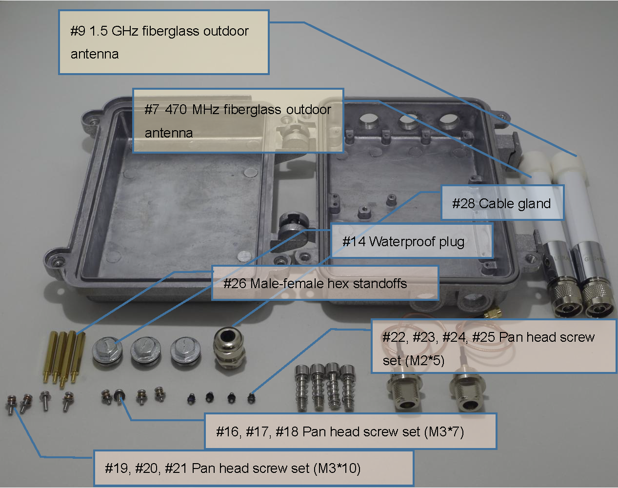
1. Assembling
You can make your first ChirpBox node here.
1.1 Shield assembling
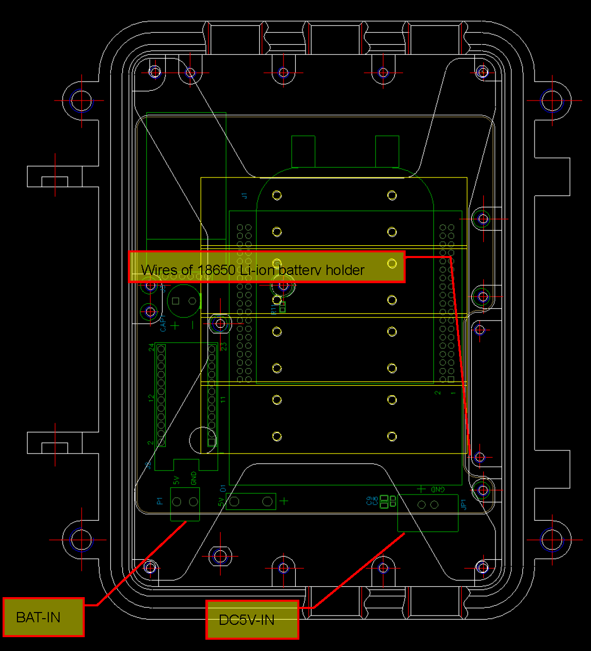
1. Get the wires (two pairs of red and blue wires) well connected to the two wire connectors (BAT-IN and DC5V-IN) on the customized base board [#11].
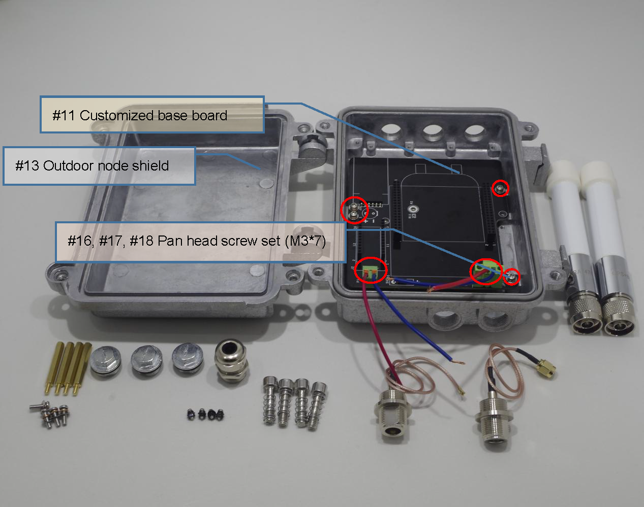
2. Install the customized base board [#11] in the outdoor node shield [#13] by using the pan head screw set [#16, #17, #18].
3. Install male-female hex standoffs [#26]. The thread locker [#28] is recommended to be used.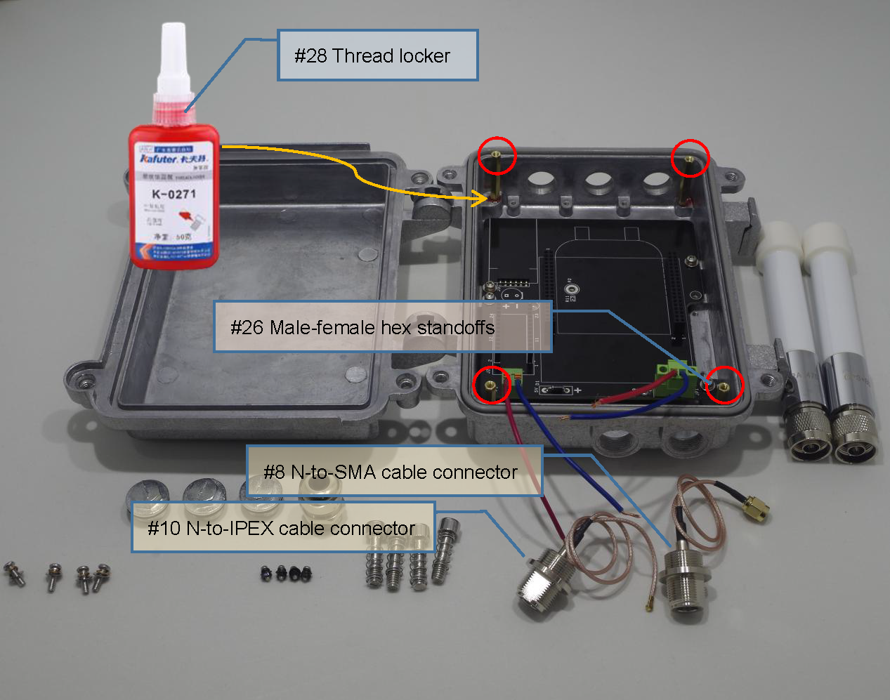
4. Install radio frequency cable connectors [#8, #10] (as shown above) in the outdoor node shield [#13].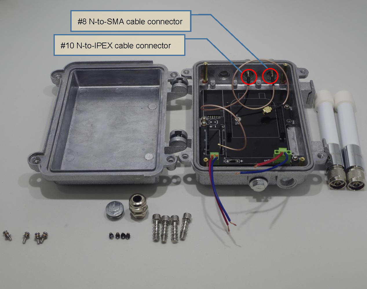
1.2 Components assembling
5. Install the processor board [#1], the GNSS module [#3] and the RTC module [#4].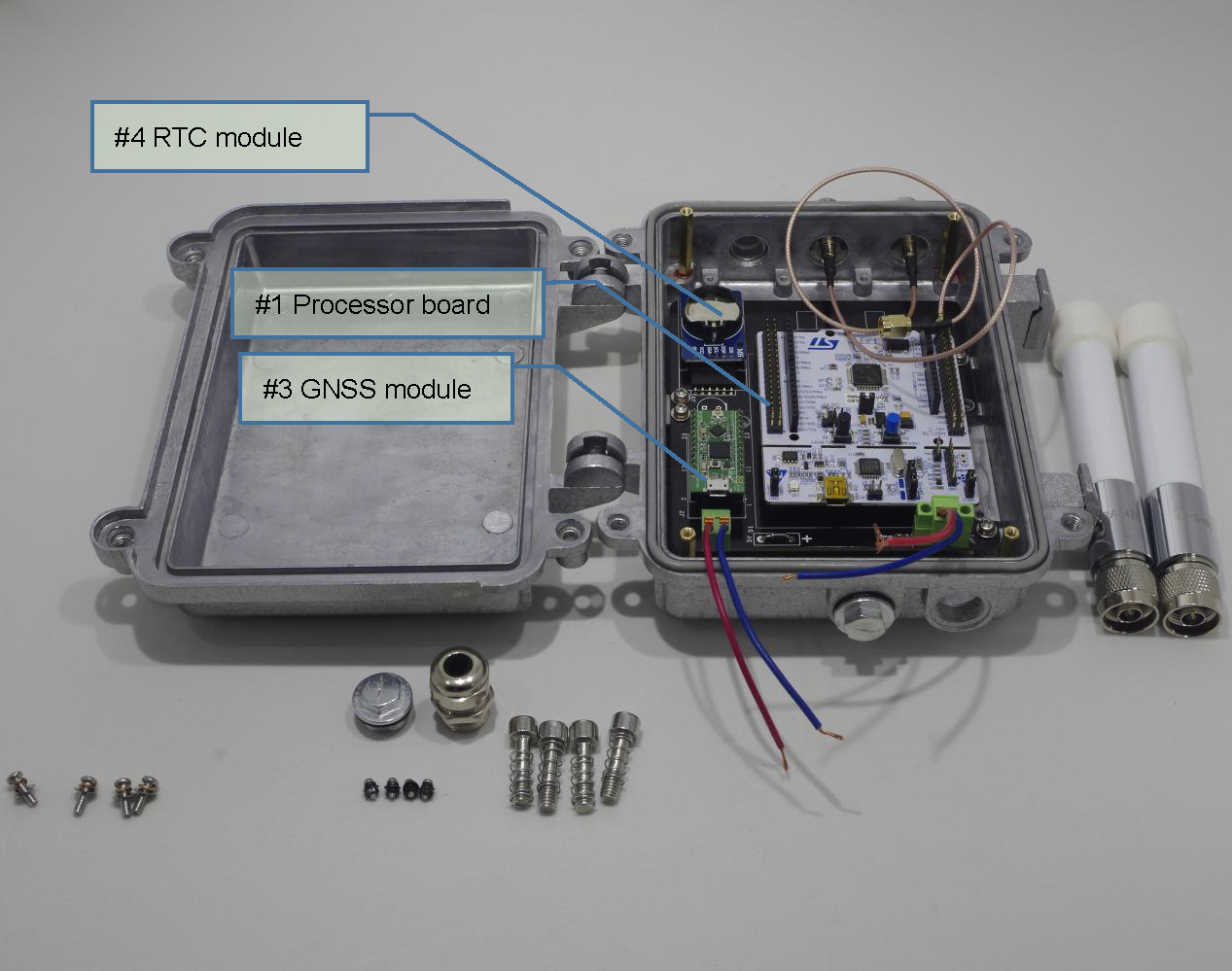
6. Install the LoRa transceiver board [#2]. Get the N-to-SMA cable connector [#8] connected to the LF port on the LoRa transceiver board [#2]. Get the N-to-IPEX cable connector [#10] to the GNSS module [#3].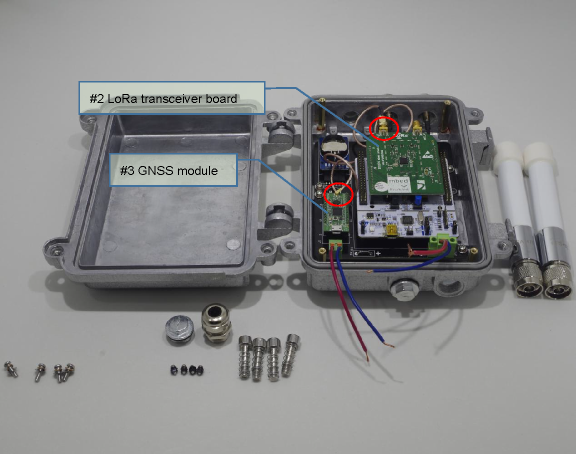
1.3 Power supply assembling
7. Use the pan head screw set (M2*5) [#22, #23, #24, #25] to install the 18650 Li-ion battery holder [#5] on the front side of customized mounting plate [#15].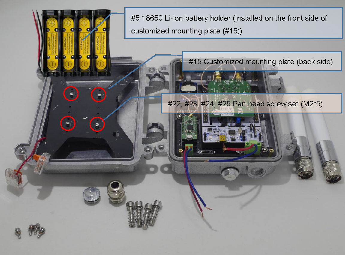
8. Install the customized mounting plate [#15] with the pan head screw set (M3*10) [#19, #20, #21] and the male-female hex standoffs [#26] (which have been installed in step 3, 1.1).
9. Connect the wires of the 18650 Li-ion battery holder [#5] and the wires of BAT-IN on the customized base board [#11] with the wire quick connectors [#12]. Specifically, the 5V of the BAT-IN is connected to the anode of the battery holder; the GND is connected to the cathode.
10. Put 2 waterproof plugs [#14] on the shield [#13] if there is no need to use a DC adapter (i.e., only battery powered). Put 18650 Li-ion batteries [#6] in the holder [#5].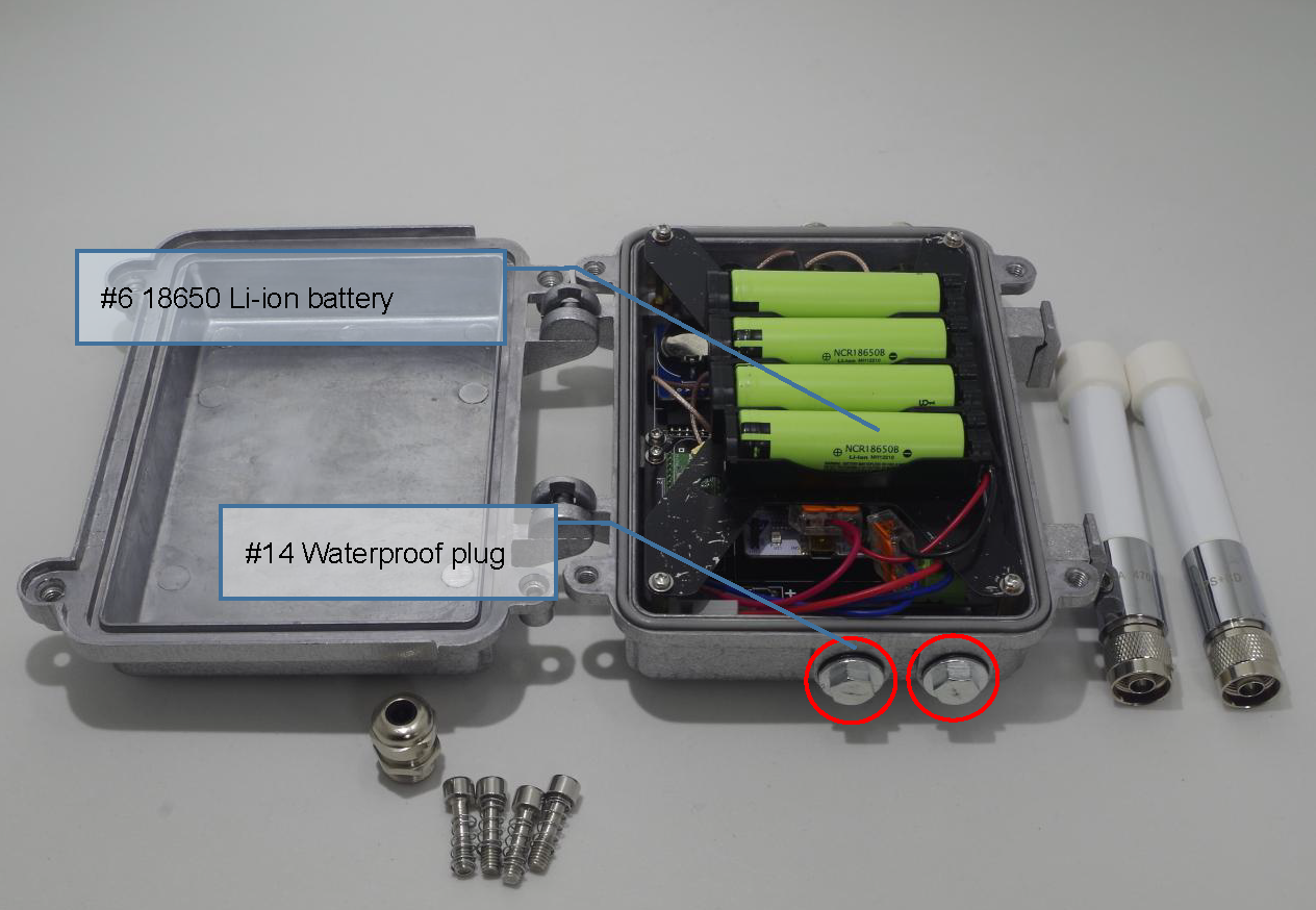
Alternative: When the DC adaptor is used, no battery is necessary. Install the cable gland [#27] on shield [#13] instead of the waterproof plug [#14], and thread the wires of a DC adapter (e.g., the power and the ground wires of a 5V/2A DC adapter) through it.
Connect the wires of the DC adapter and the wires of DC5V-IN on the customized base board [#11] with the wire quick connectors [#12]. Specifically, “+” of the DC5V-IN is connected to the positive of the adapter; the GND is connected to the negative.
NOTICE: No battery should be installed if a DC adapter is required. Batteries CANNOT be charged in the ChirpBox node since there is no charging management circuit in the battery holder [#5].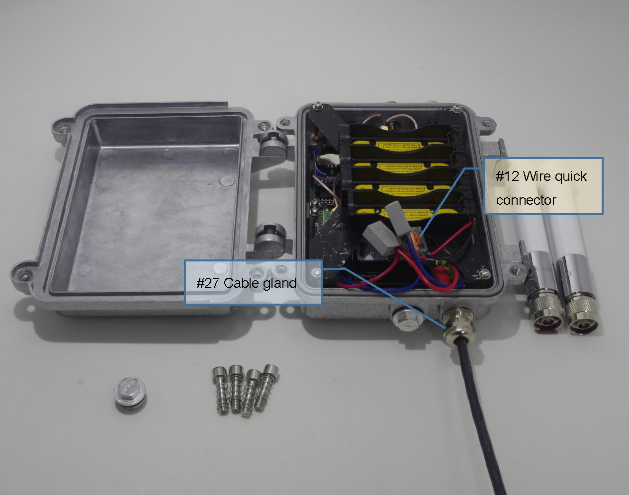
1.4 Antenna assembling
11. Close and lock the outdoor node shield [#13]. Install the 470 MHz fiberglass outdoor antenna [#7] and 1.5 GHz fiberglass outdoor antenna [#9], respectively.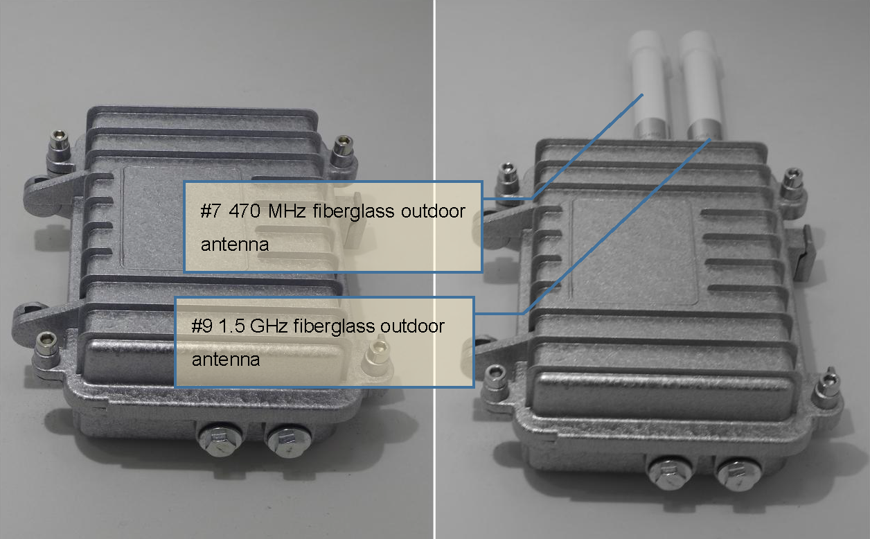
2. Programming
2.1 Prerequisites
1. Hardware:
- A computer (with Windows 10)
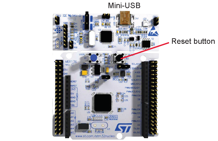
- Mini-USB cable (connecting with STM32L476RG)
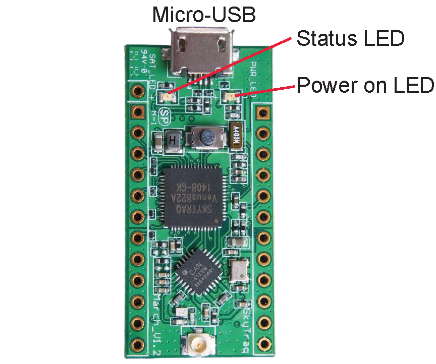
- Micro-USB cable (connecting with NavSpark)
2. Software:
- Environment:
- Python 3.x. for running scripts provided by ChirpBox.
We can prepare the following free tools to program binary files and debugging.
Programming tools:
- STM32 ST-LINK Utility (Windows) for programming STM32L476RG
- Arduino IDE (Windows) for programming NavSpark
Serial terminal:
- Tera Term (Windows)
Other debugging tool:
- GNSS Viewer (Windows) and Arduino IDE (Windows) for debugging NavSpark
2.2 Firmware configuration
1. STM32L476RG:
Obtain the unique device ID (UID)
- Clone the ChirpBox repository here.
- Connect the STM32L476RG board to the PC via mini-USB port.
- Open STM32 ST-LINK Utility, select firmware
daemon.bininChirpBox/Daemon/and program it to the STM32L476RG board. - Open serial terminal and reset the device by pushing the reset button manually, the UID of the node would be output. For example, if the UID is
0x012345, the output would be shown as follows:Starting node 0x012345.
Specifying firmware
- Update
node_listinChirpBox/chirpbox manager/daemon_config.jsonwith the obtained UID. For example, now we have nodes0x012345,0x012346, and0x012347:1
2
3{
"node_list": "0x012345, 0x012346, 0x012347"
} - Run
daemon_generatetool underChirpBox/chirpbox manager/to update the specified daemon firmware.1
python cbmng.py -daemon_generate
- Program the updated
daemon.binto the STM32L476RG board.
- Update
2. NavSpark:
- Connect the NavSpark board to the PC via mirco-USB port.
- Program the NavSpark firmware using GNSS Viewer (see detailed steps here).
- Put the file
Chirpbox\Miscellaneous\SimpleFIFO.hinto your Arduino IDE Library, for exampleArduino15\packages\navspark\hardware\navspark\1.0.4\cores\arduino. - Program
Chirpbox\Miscellaneous\GNSS_firmware.inowith Arduino IDE.
3. Running
3.1 Node deployment
1. Pre-deployment:
- Open serial terminal, reset the device, check whether a proper node ID is allocated. If the node ID has been allocated:
Running with node ID: 1
otherwise the ChirpBox node would output (if the UID of the node is 0x012345):Warning: node mapping not found for node 0x012345!!!
and please repeat steps in 2.2 Firmware configuration for a correct node ID. - Make sure the power on LED (green) and status LED (blue) of NavSpark are ON.
2. Deployment:
- Select the first UID node in
node_listas the control node, and connect it to your computer with GNSS signal. - Put the others as target nodes outdoors.
- Wait until the NavSpark’s status LED (blue) is turned OFF, which indicates the target node has obtained GNSS signal and been synchronized with the control node.
3.2 Manage nodes remotely
- Get all deployed nodes’ status (daemon firmware version and battery voltage level):
Switch the directory toChirpBox/chirpbox manager/
And run the following command:Here, COM_port is serial port connected with the control node.1
python cbmng.py -colver COM_port
- So far, we have run the ChirpBox. Please see Start an experiment with the script for more ChirpBox management options.